A chiller is simply a device that is used to remove heat from something. For industrial purposes, chillers can be thought of as a component within a complex mechanical system that is used to remove heat from a process or substance. To really understand what a chiller is, a fundamental knowledge of the principles of basic refrigeration is required.
An industrial chiller is a specialized mechanical system designed to remove heat from a process or substance, such as water or coolant, to maintain a precise operating temperature. This is achieved by utilizing the vapor-compression refrigeration cycle to transfer unwanted heat away from the production environment.
Before getting into the fundamentals of refrigeration, a few basic definitions should be considered:
A). Heat is a form of energy transferred by virtue of a difference in temperature. Heat exists everywhere to a greater or lesser degree. As a form of energy it can be neither created or destroyed, although other forms of energy may be converted into heat, and vice versa. It is important to remember that heat energy travels in only one direction; from a warmer to a cooler object, substance, or area.
B). Cold is a relative term referring to the lack of heat in an object, substance, or area. Another definition describes it as the absence of heat, no process yet has been devised of achieving "absolute zero," the state in which all heat has been removed from any object, substance, or area. Theoretically this zero point would be 459.69 degrees below zero on the Fahrenheit thermometer scale, or 273.16 degrees below zero on the Celsius thermometer scale.
C). Refrigeration, or cooling process, is the removal of unwanted heat from a selected object, substance, or space and its transfer to another object, substance, or space. Removal of heat lowers the temperature and may be accomplished by use of ice, snow, chilled water or mechanical refrigeration.
D). Mechanical refrigeration, is the utilization of mechanical components arranged in a "refrigeration system" for the purpose of transferring heat.
E). Refrigerants, are chemical compounds that are alternately compressed and condensed into a liquid and then permitted to expand into a vapor or gas as they are pumped through the mechanical refrigeration system to cycle.
The refrigeration cycle is based on the long known physical principle that a liquid expanding into a gas extracts heat from the surrounding substance or area. (You can test this principle by simply wetting your finger and holding it up. It immediately begins to feel cooler than the others, particularly if exposed to some air movement. That's because the liquid in which you dipped it is evaporating, and as it does, it extracts heat from the skin of the finger and air around it).
Refrigerants evaporate or "boil" at much lower temperatures than water, which permits them to extract heat at a more rapid rate than the water on your finger.
F). Refrigeration system fundamental components.
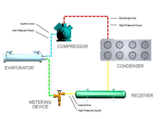
The job of the refrigeration cycle is to remove unwanted heat from one place and discharge it into another. To accomplish this, the refrigerant is pumped through a closed refrigeration system. If the system was not closed, it would be using up the refrigerant by dissipating it into the surrounding media; because it is closed, the same refrigerant is used over and over again, as it passes through the cycle removing some heat and discharging it. The closed cycle serves other purposes as well; it keeps the refrigerant from becoming contaminated and controls its flow, for it is a liquid in some parts of the cycle and a gas or vapor in other phases.
Let's look at what happens in a simple refrigeration cycle, and to the major components involved. Two different pressures exist in the cycle - the evaporating or low pressure in the "low side," and the condensing, or high pressure, in the "high side." These pressure areas are separated by two dividing points: one is the metering device where the refrigerant flow is controlled, and the other is at the compressor, where vapor is compressed.
The metering device is a point where we will start the trip through the cycle. This may be a thermal expansion valve, a capillary tube, or any other device to control the flow of refrigerant into the evaporator, or cooling coil, as a low-pressure, low-temperature refrigerant. The expanding refrigerant evaporates (changes state) as it goes through the evaporator, where it removes the heat from the substance or space in which the evaporator is located.
Heat will travel from the warmer substance to the evaporator cooled by the evaporation of the refrigerant within the system, causing the refrigerant to "boil" and evaporate, changing it to a vapor. This is similar to the change that occurs when a pail of water is boiled on the stove and the water changes to steam, except that the refrigerant boils at a much lower temperature.
Now this low-pressure, low-temperature vapor is drawn to the compressor where it is compressed into a high-temperature, high-pressure vapor. The compressor discharges it to the condenser, so that it can give up the heat that it picked up in the evaporator. The refrigerant vapor is at a higher temperature than the air passing across the condenser (air-cooled type); or water passing through the condenser (water-cooled type); therefore that is transferred from the warmer refrigerant vapor to the cooler air or water.
In this process, as heat is removed from the vapor, a change of state takes place and the vapor is condensed back into a liquid, at a high-pressure and high-temperature.
The liquid refrigerant travels now to the metering device where it passes through a small opening or orifice where a drop in pressure and temperature occurs, and then it enters into the evaporator or cooling coil. As the refrigerant makes its way into the large opening of the evaporator tubing or coil, it vaporizes, ready to start another cycle through the system.
The refrigeration system requires some means of connecting the basic major components - evaporator, compressor, condenser, and metering device - just as roads connect communities. Tubing or "lines" make the system complete so that the refrigerant will not leak out into the atmosphere. The suction line connects the evaporator or cooling coil to the compressor, the hot gas or discharge line connects the compressor to the condenser, and the liquid line is the connecting tubing between the condenser and the metering device (Thermal expansion valve). Some systems will have a receiver immediately after the condenser and before the metering device, where the refrigerant is stored until it is needed for heat removal in the evaporator.
There are many different kinds and variations of the refrigeration cycle components. For example, there are at least a half dozen different types of compressor, from the reciprocating, piston through a screw, scroll and centrifugal impeller design, but the function is the same in all cases - that of compressing the heat laden vapor into a high-temperature vapor.
The same can be said of the condenser and evaporator surfaces. They can be bare pipes, or they can be finned condensers and evaporators with electrically driven fans to pass the air through tem, or with a condenser pump to pump the water through a water-cooled condenser.
There are a number of different types of metering devices to regulate the liquid refrigerant into the evaporator, depending on size of equipment, refrigerant used, and its application.
The mechanical refrigeration system described above is essentially the same whether the system be a domestic refrigerator, a low-temperature freezer, comfort air conditioning system, industrial chiller, or commercial cooling equipment. Refrigerants will be different and size of the equipment will vary greatly, but the principle of operation and the refrigeration cycle remains the same. Thus, once you understand the simple actions that are taking place within the refrigeration mechanical cycle you should have a good understanding how a refrigeration system works.
Disclaimer - While Berg Chilling Systems Inc. ("Berg") makes reasonable efforts in providing accurate information, we make no representations or warranties regarding the accuracy of any content therein. We assume no liability or responsibility for any typographical, content or other errors or omissions. We reserve the right to modify the content of this documentation without advance notice.
A). STATES OF MATTER
All known matter exists in one of three physical forms or states: solid, liquid, or gaseous. There are distinct dissimilarities among these physical states namely:
Matter in a liquid state will retain its quantity and size but not its shape. The liquid will always conform to the occupying container. If a cubic foot of water in a container measuring 1 foot on each side is transferred to a container of different rectangular dimensions, the quantity and volume of the water will be the same although the dimension will change.
Matter in solid state will retain its quantity, shape, and physical dimensions. A cubic foot of wood will retain its weight, size, and shape even if moved from place to place.
Matter in gaseous state does not have a tendency to retain either its size or its shape. If a one foot cylinder containing steam or some other gas is connected to a 2-cubic foot cylinder on which a vacuum has been drawn, the vapor will expand to occupy the volume of the large cylinder. Although these specific differences exist in the three states of matter, quite frequently, under changing conditions of pressure and temperature, the same substance may exist in any one of the three states, such as a solid, a liquid, or vapor (ice, water, and steam, for example). Solids always have some definitive shape, whereas liquids and gases have no definitive shape of their own, but will conform to the shape of their containers.
B). MOLECULAR MOVEMENT
All matter is composed of small particles known as molecules, for the present we will concern ourselves only with the molecule, the smallest particle into which any matter or substance can be broken down and still retain its identity. Molecules vary in shape, size, and weight. In physics we learn that molecules have a tendency to cling together. When heat energy is applied to a substance it increases the internal energy of the molecules, which increase their motion or velocity of movement. With this increase in the movement of the molecules, there is also rise or increase in the temperature of the substance. When heat is removed from a substance, it follows that the velocity of the molecular movement will decrease and also that there will be a decrease or lowering of the internal temperature of the substance.
C). CHANGE OF STATE
When a solid substance is heated, the molecular motion is chiefly in the form of rapid motion back and forth, the molecules never moving far from their normal or original position. But at some given temperature for that particular substance, further addition of heat will not necessarily increase the molecular motion within the substance; instead, the additional heat will cause some solids to liquefy (change into a liquid). Thus the additional heat causes a change of state in the material.
The temperature at which this change of state in a substance takes place is called its melting point. Let us assume that a container of water at 70 deg F, in which a thermometer has been placed, is left in the freezer for hours. When it is taken from the freezer, it has become a block of ice - solidification has taken place. Let us further assume that the thermometer in the ice block indicates a temperature of 20 deg F.
If it is allowed to stand at room temperature, heat from the room air will be absorbed by the ice until the thermometer indicates a temperature of 32 deg F, when some of the ice will begin to change into water. With heat continuing to transfer from the room air to the ice, more ice will change back into the water; but the thermometer will continue to indicate a temperature a temperature of 32 deg F until all the ice has melted. Liquefaction has now taken place.
As mentioned, when all the ice is melted, the thermometer will indicate a temperature of 32ºF, but the temperature of the water will continue to rise until it reaches or equals room temperature. If sufficient heat is added to the container of water through outside means such as a burner, the temperature of the water will increase until it reaches 212ºF, at this temperature, and under "standard" atmospheric pressure, another change will take place - vaporization. Some of the water will vaporize into steam and, with the addition of more heat, all of the water will vaporize into steam; yet the temperature of the water will not increase above 212ºF.
Thus far we have learned how solids can change into liquid, and how a liquid can change in to a vapor but it is possible for a substance to undergo a physical change through which solid will change directly into a gaseous state without first melting into a liquid. This is known as a sublimation. As an example, dry ice (CO2) at atmospheric conditions sublimes directly into vapor. Let us review these changes of state: a) SOLIDIFICATION - a change from a liquid to a solid. LIQUEFACTION - a change from a solid to a liquid. VAPORIZATION - a change from a liquid to a vapor. CONDENSATION - a change from a vapor to a liquid. SUBLIMATION - a change from a solid to a vapor without passing through the liquid state.
MEASUREMENTS
Most of us are acquainted with common measurement, such as those pertaining to length, weight, volume, etc.; but now we move into other types of measurement, such as those of heat intensity, heat quantity, and energy conversion units.
HEAT INTENSITY
Heat is a form of energy which is not measurable in itself; but the heat intensity, or temperature of a substance, can be measured. A unit of the intensity of heat is called the degree, measured on the temperature scale. In the discussion of state of matter, temperature was discussed, as was the addition or removal of heat. Relatively, water is colder than steam; yet it is, at the same time, warmer than ice. Temperature scales were formulated through use of glass tubes with similar interior diameter and reservoir for the liquid - such as mercury - that will expand and rise up in the tube when heated.
The Fahrenheit thermometer or scale is based on the relative position of the mercury in the thermometer when water is at the freezing point and when water is boiling. the distance between these two points was divided into 180 equal portions or parts called degrees. The point where water either will freeze, or ice will melt, under normal atmospheric conditions, was labeled as 32 degrees; whereas the location, or point on the thermometer where water will boil was labeled 212 degrees; whereas the thermometer has been the one most commonly used in most types of refrigeration engineering work. A Celsius thermometer formerly called a Centigrade thermometer, is used in chemistry and physics, especially in continental Europe, south Americas and Asia.
A frequently asked question is why the boiling point of water and the melting point of ice where used as the standard for both thermometers. These points or temperatures were chosen because water has a very constant boiling and freezing temperature, and water is a very common substance.
TEMPERATURE CONVERSION
Most frequently a conversion from one temperature scale to other is made by the use of a conversion table, but if one is not available, the conversion can be done easily by a formula using these equations:
(2-1) Deg. F = 1.8 ºC + 32
Deg. F = 5/9 ºC + 32
(2-2) Deg. C = (ºF - 32)/1.8
Deg. C = 5/9(ºF - 32)
Thus far, in measurement of heat intensity, we have located two definitive reference points - the freezing point and the boiling point of water on both the Fahrenheit and Celsius scales. We now must locate still a third definite point - absolute zero. This is the point where, it is believed all molecular action ceases. As already noted on the Fahrenheit temperature scale, this is about 460 Deg. below zero, -460 Deg. F, while on the Celsius scale it is about 273 Deg. below zero, or -273 Deg. C. Certain basic laws, are based on the use of absolute temperatures. If a Fahrenheit reading is given, the addition of 460 Deg. to this reading will convert it to Degrees Rankin or Deg. R; whereas if the reading is from the Celsius scale, the addition of 273 Deg. will convert it to degrees Kelvin, Deg. K.
HEAT QUANTITY
Heat quantity is different from heat intensity, because it takes into consideration not only the temperature of the fluid or substance being measured but also its weight. The unit of heat quantity is the British thermal unit (Btu). Water is used as a standard for this unit of heat quantity; a Btu is the amount of heat required to raise the temperature of one pound of water by one degree Fahrenheit at sea level.
Two Btu will cause a change in temperature of two degrees Fahrenheit of one pound of water; or it will cause a change in temperature of one degree Fahrenheit of two pounds of water. Therefore, when considering a change in temperature of water, the following equation may be utilized:
(2-3) Btu = W x TD
Where Change in heat (in Btu) = Weight (in pounds) x Temperature Difference.
SPECIFIC HEAT
The specific heat of a substance is the quantity of heat in Btu's required to change the temperature of one pound of substance one degree Fahrenheit. Btu is the amount of heat necessary to increase the temperature of one pound water one degree Fahrenheit, or to lower the temperature of the same weight of water by the same unit of measurement on a thermometer.
Therefore, the specific heat of water is 1.0; and water is the basis for the specific heat table in figure 2-8
| Water | 1.00 |
| Ice | 0.50 |
| Air (dry) | 0.24 |
| Steam | 0.48 |
| Aluminum | 0.55 |
| Brass | 0.09 |
| Lead | 0.03 |
| Iron | 0.10 |
| Mercury | 0.03 |
| Copper | 0.09 |
| Alcohol | 0.60 |
| Kerosene | 0.50 |
| Olive oil | 0.47 |
| Salt Brine 20% | 0.85 |
| R-22 | 0.26 |
| R-12 | 0.21 |
Fig. 2-8 Specific Heat of Common substances Btu/lb/ºF.
You will see that different substances vary in their capacity to absorb or give up heat. The specific heat values of most substances will vary with a change in temperature; some vary only a slight amount, while others can change considerably.
Suppose that two containers are placed on a heating element or burner side by side, one containing water and the other an equal amount, by weight, of olive oil. You would soon find that the temperature of the olive oil increases at a more rapid rate than that of the water, demonstrating that olive oil absorbs heat more rapidly than water.
If the rate of the temperature increase of the olive oil was approximately twice that of the water, it could be said that olive oil requires only half as much heat as water to increase its temperature one degree Fahrenheit. Based on the value 1.0 for the specific heat of water, it would show that the specific heat of olive oil must be approximately 0.5, or half that of water. (The table of specific heat of substances shows that olive oil has a value of 0.47).
Equation (2-3) from previous discussion can now be stated as:
(2-4) Btu = W x c x TD
Where c = specific heat of a substance; W = the weight of substance; and TD = temperature difference.
The specific heat of a substance also will change, with a change in the state of substance. Water is a very good example of this variation in specific heat. Specific heat of water is 1.0; but as solid ice, its specific heat approximates 0.50; and a similar value is applied to steam 0.48; the gaseous state of the water.
Example: determine the amount of Btu which must be removed to cool 40 lb. of 20% salt brine from 60ºF to 20ºF.
Btu = W x c x TD
Btu = 40 lb. x 0.85 x (60ºF - 20ºF)
Btu = 1360
SENSIBLE HEAT
Heat that can be felt or measured is called sensible heat. It is the heat that causes a change in temperature of a substance, but not a change in state. Substances, whether in a solid, liquid, or gaseous state, contain sensible heat to some degree, as long as their temperatures are above absolute zero. Equations used for solution of heat quantity, and those used in conjunction with specific heats, might be classified as being sensible heat equations, since none of them involve any change of state.
LATENT HEAT
Under a change of state, most substances will have a melting point at which they will change from solid to a liquid without any increase in temperature. At this point, if the substance is in a liquid state and heat is removed from it, the substance will solidify without a change in its temperature. The heat involved in either of these processes (changing from a solid to a liquid or from liquid to a solid), without a change in temperature, is known as the latent heat of fusion.
Figure 2-9 shows the relationship between temperature in Fahrenheit degrees and both sensible and latent heat in Btu's.
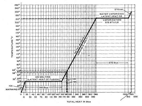
As pointed out earlier, the specific heat of water is 1.0 and that of ice is 0.50, which is the reason for the difference in slope of the lines denoting the solid (ice) and liquid (water). To increase the temperature of the ice from -40ºF to 32ºF requires only 36 Btu of heat. (-40ºF to 32ºF = 72ºF temperature change). (Btu = 1 lb. x 0.50 x 72 = 36). From B to C, 144 Btu were added to melt the ice. The temperature did not change from B to C. From C to D, 180 Btu were added to heat the water from 32ºF to 212ºF. From D to E, 970 Btu were added to vaporize water. Note that the temperature did not change form D to E.
The derivation of the word latent is from the Latin word for hidden. This is hidden heat, which does not register on the thermometer, nor can it be felt. Needless to say, there is no increase or decrease in the molecular motion within the substance, for it would show up as a change in temperature on a thermometer.
(2-6) Btu = (W1 x c1 x TD1)
+ (W1 x latent heat)
+ (W2 x c2 x TD2)
Another type of latent heat that must be taken into consideration when total heat calculations are necessary is called latent heat of vaporization. This is the heat that one pound of a liquid absorbs while being changed into the vapor stage. Or it can be classified as the latent heat of condensation; for, when sensible heat is removed from the vapor to the extent that it reaches the condensing point, the vapor condenses back into the liquid form.
The absorption of the amount of heat necessary for the change of state from a liquid to a vapor by evaporation, and the release of that amount of heat necessary for the change of state from a vapor back to the liquid by condensation are the main principles of the refrigeration process, or cycle. Refrigeration is the transfer of heat by the change in state of the refrigerant.
SECOND LAW OF THERMODYNAMICS
The second law of thermodynamics, states that heat transfer in only one direction - downhill; and this takes place through one of the three basic methods of heat transfer. A. Conduction, B. Convection, C. Radiation.
CONDUCTION
Conduction is described as the transfer of heat between closely-packed molecules of the substance, or between substances that are touching or in good contact with one another. When the transfer of heat occurs in a single substance, such as a metal rod with one end in a flame, movement of heat continues until there are is a temperature balance throughout the length of the rod.
If the rod is immersed in water, the rapidly moving molecules on the surface of the rod will transmit some heat to the molecules of water, and still another transfer of heat by conduction takes place. As the outer surface of the rod cools off, there is still some heat within the rod, and this will continue to transfer to the outer surfaces of the rod and then to the water, until a temperature balance is reached.
The speed with which heat will transfer by means of conduction will vary with different substances or materials if the substances or materials are of the same dimensions. The rate of heat transfer will vary according to the ability of the materials or the substances to conduct heat. Solids, on the whole, are much better conductors than liquids; and in turn, liquids conduct heat better than gases or vapors.
Most metals, such as gold, silver, copper, steel, and iron, conduct heat fairly rapidly, whereas other solids such as glass, wood, polyurethane, or other fibrous building materials transfer heat at a much slower rate and are therefore used as insulators.
Copper is an excellent conductor of heat, as is aluminum. These substances are ordinarily used in refrigeration evaporators, condensers, and refrigeration pipes connecting the various components of a refrigerant system, although iron and carbon steel is occasionally used with some large refrigerant installations.
The rate at which the heat may be conducted through various materials is dependent on such factors as (a) thickness of material, (b) its cross-sectional area, (c) the temperature difference between the two sides of the material, (d) the heat conductivity (k factor) of the material, and (e) the time duration of the heat flow.
| Material | Conductivity (k) |
| Plywood | 0.80 |
| Glass Fiber-organic bonded | 0.25 |
| Expanded polystyrene insulation | 0.25 |
| Expanded polyurethane insulation | 0.16 |
| Cement Mortar | 5.0 |
| Stucco | 5.0 |
| Brick (common) | 5.0 |
| Hard woods (maple, oak) | 1.10 |
| Soft woods (fir, pine) | 0.80 |
| Gypsum Plaster (Sand aggregate) | 5.6 |
NOTE: The k factors are given in Btu/hr/ft sq/ºF/in. of thickness of the material. These factors may be utilized through use of the following equation:
(2-7) Btu =(A x k x TD)/X
Where: A = Cross-sectional area in ft sq. k = Heat conductivity in Btu/hr. TD = Temperature difference between the two sides. X = Thickness of material in inches.
Metals with a high conductivity are used within the refrigeration system itself because it is desirable that rapid transfer of heat occur in both evaporator and condenser. The evaporator is where heat is removed from the conditioned space or substance; the condenser dissipates this heat to another medium or space.
In the case of the evaporator, the substance or air is at a higher temperature than the refrigerant within the tubing and there is a transfer of heat downhill; whereas in the condenser the refrigerant vapor is at a higher temperature than the cooling medium traveling through the condenser, and here again there is a downhill transfer of heat.
Plain tubing, whether copper, or aluminum, or another metal, will transfer heat according to its conductivity or k factor, but this heat transfer can be increased through addition of fins on the tubing. They will increase the area of heat transfer surface, thereby increasing the overall efficiency of the system. If additions of fins doubles the surface area, it can be shown by the use of Eq. (2-7) that the overall heat transfer should itself be doubled, when compared to that of plain tubing.
CONVECTION
Another means of heat transfer is by motion of the heated material itself and is limited to liquid or gas. When a material is heated, convection currents are set up within it, and the warmer portions of it rise, since heat brings about the decrease of a fluid's density and an increase of its specific volume.
Air within a refrigerator and water being heated in a pan are prime examples of the result of convection currents. The air in contact with the cooling coil on a refrigerator becomes cool and therefore more dense, and begins to fall to the bottom of the refrigerator. In doing so, it absorbs heat from the product and the walls of the refrigerator, which, through conduction, has picked up heat from the room.
After heat has been absorbed by the air it expands, becoming lighter, and rises until it again reaches the cooling coil where heat is removed from it. The convection cycle repeats as long as there is a temperature difference between the air and the coil. In commercial-type units, baffles may be constructed within the box in order that the convection currents will be directed or take the desired patterns of air flow around the cooling coil.
Water heated in a pan will be affected by the convection currents set up within it through application of heat. The water nearest the heat source, in absorbing heat, becomes warmer and expands. As a result it becomes lighter, it rises and is replaced by the cooler more dense water. This process will continue until all of the water is at the same temperature.
Convection currents as explained here are natural, and, as is the case of the refrigerator, a natural flow is a slow flow. In many cases, convection must be increased through use of fans or blowers and, in the case of liquids, pumps are used for forced circulation to transfer heat from one place to another.
RADIATION
A third means of heat transfer is through radiation by waves similar to light or sound waves. The sun's rays heat the earth by means of radiant heat waves, which travel in a straight path without heating the intervening matter of air. The heat from a light bulb or from a hot stove is radiant in nature and is felt by those near them, although the air between the source and the object, which the rays pass through, is not heated. If you have been relaxing in the shade of a building or a tree on a hot sunny day and move into direct sunlight, the direct impact of the heat waves will hit like a sledge hammer even though the air temperature in the shade is approximately the same as in the sunlight.
Al low temperatures there is only a small amount of radiation, and only minor temperature differences are noticed; therefore radiation has very little effect in actual process of refrigeration itself. But results of radiation from direct solar rays can cause an increased refrigeration load in a building air conditioning system. Radiant heat is readily absorbed by dark or dull materials or substances, whereas light-colored surfaces or materials will reflect radiant heat waves, just as they do light rays.
When radiant heat or energy (since all heat is energy) is absorbed by a material or substance it is converted into sensible heat - that which can be felt or measured. Every body or substance absorbs radiant energy to some extent, depending upon the temperature difference between the specific body or substance and other body or substances. Every substance will radiate energy as long as its temperature is above absolute zero and another substance within its proximity is at a lower temperature.
INSULATION
Any material that deters or helps to prevent the transfer of heat by any means is called and may be used as insulation. Of course, no material will stop completely the flow of heat. If there were such a substance, it would be very easy to cool a given space down to desired temperature and keep it there.
such substances as cord, glass fibers, mineral wool, polyurethane and polystyrene foams are good examples of insulating materials; but numerous other substances are used in insulating refrigerated spaces or buildings.
Insulation should be fire and moisture resistant, and also vermin proof. Low temperature components and boxes require an insulation that is vapor-resistant, such as unicellular foam, so that water vapor will not readily penetrate through into the insulation and condense there, reducing the insulating efficiency.
REFRIGERATION EFFECT - "TON"
A common term that has been used in refrigeration work to define and measure capacity or refrigeration effect is called a ton of refrigeration. It is the amount of heat absorbed in melting a tone of ice (2,000 lb) over a 24-hour period.
The ton of refrigeration is equal to 288,000 Btu. This may be calculated by multiplying the weight of ice (2,000 lb) by the latent heat of fusion (melting) of ice (144 Btu/lb). Thus
2.000 lb x 144 Btu/lb = 288,000 Btu
in 24 hours or 12,000 Btu per hour (288,000 / 24). Therefore, one ton of refrigeration = 12,000 Btu/hr.
SUMMARY
The change of state of matter can be effected by adding or taking away heat. Heat effect or intensity can be measured by the use of thermometers. Heat always travels from a warmer condition to a cooler condition. Substances have different capacities to absorb heat. Heat exists in two forms: sensible and latent. The unit of measure to express heat quantity is the Btu. Heat can be transferred by several methods: conduction, convection and radiation. An insulator is a substance that will retard the flow of heat.
Disclaimer - While Berg Chilling Systems Inc. ("Berg") makes reasonable efforts in providing accurate information, we make no representations or warranties regarding the accuracy of any content therein. We assume no liability or responsibility for any typographical, content or other errors or omissions. We reserve the right to modify the content of this documentation without advance notice.
Fluid is "any substance that can flow, liquid or gas." Refrigerant may be classified as fluid, since, within the refrigeration cycle, it exists both as a liquid and as a vapor or gas.
FLUID PRESSURE
The weight of a wood or any other solid material acts as a force downward on whatever is supporting it. The force of this solid object is the overall weight of the object, and the total weight is distributed over the area upon which it lies.
The weight of a given volume of water, however, acts not as a force downward on the bottom of the container holding it, but also as a force laterally on the sides of the container. If a hole is made in the side of the container below the water level, the water above the hole will be forced out because of its acting downward and sideways.
Fluid pressure is the force per unit area that is exerted by gas or a liquid. It is usually expressed in terms ofPsi (pound per square inch). It varies directly with the density and the depth of the liquid, and, at the same depth below the surface, the pressure is equal in all directions. Notice the difference between the terms used: force and pressure. Force means the total weight of the substance; pressure means the unit force or pressure per square inch.
(3-1) Pressure = Force/Area or P = F/A
HEAD
Pressure and depth have a close relationship when a fluid is involved. In hydraulics, the depth of a body of water is called the head of water. Water pressure varies directly with its depth. If there is a decrease or increase in the head of a body of water, there will be a corresponding decrease or increase in the pressure involved, as well as the weight of the water, providing the other dimensions stay the same. This relationship can be expressed in the equation:
(3-2) p = 0.433 x h
Where p = pressure in psi; h = head in feet of water.
With this relationship between pressure and depth established, we can transpose the equation so that the depth of water in a tank can be found if we know the pressure reading at the bottom of the tank. If p = 0.433 x h, then h = p/0.433 is true, by transposition.
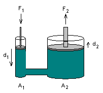
PASCAL'S PRINCIPLE
Pascal's principle, namely, that pressures applied to a confined liquid are transmitted equally throughout the liquid, irrespective of the area over which the pressure is applied. The application of this principle enabled Pascal to invent the hydraulic press, which is capable of large multiplication of force. Fig. 3-3, illustrating this principle, shows a vessel containing fluid such as oil; the vessel has a small and large cylinder connected by pipe or tubing, with a tight-fitting piston in each cylinder. If the cross-section of the small piston is 1 square inch and the area of large piston is 30 square inches, a force of 1 lb when applied to the smaller piston will support a weight of 30 lb on the large piston, because a pressure of 1 psi throughout the fluid will be exerted.
DENSITY
From a scientific or physics viewpoint, density is the weight per unit volume of a substance, and it may be expressed in any convenient combination of units of weight and volume used, such as pounds per cubic inch or pounds per cubic foot. An equation can be formulated which expresses this relationship:
(3-4) D = W/V
Where: D = density; W = weight; V = volume;
The weight, or density of water is approximately 62.4 lb per cu ft, and it can be expressed as 0.0361 lb per cu in. (1 cu ft contains 1,728 cu in., and 62.4/1,728 = 0.0361). The densities of some other common substances are listed in Fig.3-5.
| Substance | Density, lb/cu ft | Specific Gravity |
| Water (pure) | 62.4 | 1.0 |
| Ammonia (liq. 60 deg. F) | 38.5 | 0.62 |
| Aluminum | 168 | 2.7 |
| Brass | 530 | 8.5 |
| Brick (common) | 112 | 1.8 |
| Copper | 560 | 8.98 |
| Cork | 15 | 0.24 |
| Gasoline | 41.2 | 0.66 |
| Glass | 175 | 2.8 |
| Iron (cast) | 448 | 7.2 |
| Lead | 705 | 11.3 |
| Mercury | 848 | 13.6 |
| Oil (fuel) | 448.6 | 0.78 |
| Steel | 486 | 7.8 |
| Oak | 50 | 0.8 |
| Pine | 34.2 | 0.55 |
Fig. 3-5: Density and specific gravity of some common substances.
The specific gravity of any substance is the ratio of weight of a given volume of the substance to the weight of the same volume of a given substance. (Where solids or liquids are concerned water is used as a basis for specific gravity calculations, and air or hydrogen is used as a standard for gases).
Density (solid or liquid) = specific gravity x density of water (in lb/cubic foot).
Pressure within a fluid is directly proportional to the density of the fluid. This relationship can be expressed as: p = h x D
Where: p = pressure in lb per square foot; h = head or depth below the surface in feet; D = density in pounds per cubic foot.
SPECIFIC VOLUME
The specific volume of a substance is usually expressed as the number of cubic feet occupied by 1 lb of the substance. In case of liquids, it will vary with temperature and pressure. The volume of a liquid will be affected by a change in its temperature; but, since it is practically impossible to compress liquids, the volume is not affected by change in pressure.
The volume of gas or vapor is definitely affected by any change in either its temperature or the pressure to which it is subjected. In refrigeration, the volume of vapor under the varying conditions involved is most important in selection of the proper refrigerant lines and refrigerant holding vessels.
ATMOSPHERIC PRESSURE
The earth is surrounded by a blanket of air called the atmosphere, which extends 80 or more kilometers from the surface of the earth. Air has weight and also exerts pressure known as atmospheric pressure. It has been computed that a column of air, with a cross-sectional area of one square inch and extending from the earth's surface at sea level to the limits of the atmosphere, would weigh approximately 14.7 lb. force means also the weight of a substance, and pressure means unit force per square inch; therefore standard atmospheric pressure is considered to be 14.7 psi. at sea level.
This pressure is not constant; it will vary with altitude or elevation above sea level, and there will be variations due to changes in temperature as well as water vapor content of the air.
PRESSURE OF GAS
The volume of gas is affected by a change in either the pressure or temperature, or both. There are laws that govern the mathematical calculation in computing these variables.
Boyle's Law states that volume of a gas varies inversely to its pressure if the temperature of the gas remains constant. This means that the product of the pressure times the volume remains constant, or that if the pressure of the gas doubles the new volume will be one-half of the original volume. Or it may be considered that, if the volume is doubled, the absolute pressure will be reduced by one-half.
This concept may be expressed as: p1V1 = p2V2
Where: p1 = original pressure; V1 = original volume; p2 = new pressure; V2 = new volume.
It must be remembered that p1 and p2 have to be expressed in the absolute pressure terms for the above equation to be used correctly.
EXPANSION OF GAS
Most gases will expand in volume at practically the same rate with an increase in temperature, providing that the pressure does not change. And, if the gas is confined so that its volume will remain the same, the pressure in the container will increase at about the same rate as an increase in temperature.
Theoretically, if the pressure remains constant, a gas vapor will expand or contract at the rate of 1/492 for each degree of temperature change. The result of this theory would be a zero volume at a temperature of -460 deg. F, or at 0 deg. Absolute.
Charles' Law states that the volume of gas is in direct proportion to its absolute temperature, providing that the pressure is kept constant; and the absolute pressure of gas is in direct proportion to its absolute temperature, providing the volume is kept constant. That is:
(3-6) V1/V2 = T1/T2
And
(3-7) P1/P2 = T1/T2
Where: T = absolute temperature; P = absolute pressure
Or these may be expressed also as: V1T2 = V2T1 and P1T2 = P2T1
Disclaimer - While Berg Chilling Systems Inc. ("Berg") makes reasonable efforts in providing accurate information, we make no representations or warranties regarding the accuracy of any content therein. We assume no liability or responsibility for any typographical, content or other errors or omissions. We reserve the right to modify the content of this documentation without advance notice.
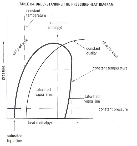
The pressure-enthalpy also called pressure-heat diagram is used to describe in engineering terms the interaction of heat, pressure, temperature, heat content, and cooling capacity of a vapor-compression system. This diagram charts pressure along the vertical axis and enthalpy (the heat content of refrigerant compared to reference value) along the horizontal axis.
Table B4 is a pressure-enthalpy diagram showing energy flow and changes of state in the vapor-compression cycle.
The curve for the refrigerant crosses several important lines and areas in the pressure enthalpy diagram:
In the all-liquid area, all refrigerant is a sub-cooled liquid.
In the all-vapor area, all refrigerant is super-heated gas.
In the liquid-vapor area (also called saturated area), refrigerant is a saturated mix of liquid and vapor. This condition is found in both the condenser and the evaporator.
The saturated liquid line separates the liquid-vapor area from the all-liquid area. Refrigerant along this line is not sub-cooled, but it becomes sub-cooled as it enters the all-liquid area.
The saturated vapor line separates the liquid-vapor area from the all-vapor area. Super-heating begins as soon as the gas moves past this line into the all-vapor area.
The line of constant quality is a line along which the refrigerant has constant proportion of gas and liquid.
The line of constant enthalpy (heat) is a vertical line along which refrigerant has equal total heat content.
The line of constant temperature marks locations along which the refrigerant has constant temperature. The line is vertical in all-liquid area, horizontal in saturated vapor area, and nearly vertical in the all-vapor area.
The line of constant pressure is a horizontal line describing location with constant pressure.
The pressure-enthalpy (heat) relationships of the refrigerant are mapped along the polygon ADEFG. The action of a vapor-compression cycle can be understood by referring to table B5.
A The hot vapor has been compressed in the compressor and is at its maximum pressure temperature, and enthalpy. Without loosing pressure, the vapor enters the condenser.
B and begins to loose the latent heat of condensation, as shown by the leftward movement (loss of enthalpy) across the diagram. The condenser pressure remains constant while the refrigerant loses heat. At
C the refrigerant is totally condensed and at the saturated liquid line. The condenser continues drawing heat from refrigerant, which finally becomes a sub-cooled liquid and begins to loose sensible heat. Now the liquid refrigerant enters the liquid line. Temperature and pressure remain constant in the liquid line until
D the metering device. Now the pressure falls suddenly along the line DE as the refrigerant re-crosses the saturated liquid line and enters the evaporator at
E the pressure is low and the liquid refrigerant begins to vaporize. After the evaporator pressure stabilizes at E, the refrigerant gains heat and boils until
F when it is entirely vaporized. Now the refrigerant is entirely vapor. This vapor begins to super-heat in the suction line until it reaches the compressor.
G The compressor squeezes the refrigerant, raising pressure, temperature, and enthalpy, and the cycle repeats as the refrigerant reaches A.

Disclaimer - While Berg Chilling Systems Inc. ("Berg") makes reasonable efforts in providing accurate information, we make no representations or warranties regarding the accuracy of any content therein. We assume no liability or responsibility for any typographical, content or other errors or omissions. We reserve the right to modify the content of this documentation without advance notice.
THE COMPRESSOR
The compressor is the mechanical heart of a refrigeration system. It causes refrigerant to flow and is where energy is applied to perform the work of removing heat in the evaporator. The compressor serves two functions. First, it regulates pressure in the evaporator by withdrawing refrigerant vapors when pressure (or temperature) is higher than desired. By regulating pressure, the evaporating temperature is fixed. Second, it compresses the gas and in doing so, adds energy or heat content to the gas. Electrical energy in the motor is exchanged for mechanical energy in the system, which, in turn, is changed into heat energy in the gas.
Compressing gas increases its temperature and decreases its specific volume (increases its density). It is essential that gas temperature be raised to a level higher than that of condensing fluid, whether it is air, water or some other liquid. Heat can flow from refrigerant to condensing medium only if there is a reasonable difference in temperature. The compressor's function is to provide that higher temperature. At the same time, an increase in gas density reduces the volume that needs to be handled in the condenser.
Compression of gas is nearly adiabatic or isentropic. This means that essentially all mechanical energy applied is converted into energy that is retained by the gas. In other words, mechanical energy is changed into heat energy, which results partly in an increase in temperature and partly in a change in molecular velocities. Both are reflected by an increase in pressure and decrease in volume. During isentropic compression, all of this mechanical energy is converted to the heat, which changes the properties of gas, and none of it is lost. At the same time, no heat is added from other sources. In an actual compressor, the gas is not insulated from its surroundings and some heat of compression is lost by conduction through metal walls of the cylinder, while at the same time heat is added from the friction of piston rings, bearings and other sources. However, the gains and losses are usually almost in balance so that the net result is close to isentropic compression.
Isentropic compression means compression at constant entropy. The entropy of gas leaving the compressor will be identical to that of gas entering the compressor. Pressure of gas as it leaves the compressor is determined by the vapor pressure of liquid refrigerant in the condenser. Assuming, that there is an open pipe between the condenser and outlet valve on the compressor cylinder and ignoring the small pressure drop that will be present, pressure in the discharge line will be constant all the way from condenser to compressor. Accordingly, in passing through the compressor, there has been an increase in temperature and heat content or enthalpy.
CAPACITY
Previously all references to changes in heat content or enthalpy have been on the basis of one pound of refrigerant. In order to relate to capacity, the element of time must be introduced. The capacity of the system depends on how often a pound of refrigerant evaporates and this depends on compressor size and on properties of the refrigerant at refrigerant cycle temperatures.
In an example with R-12, assume the compressor is of the right size to deliver one ton of refrigeration when refrigerant evaporates at 0 deg. F and is condensed at 100 deg. F. as each pound of refrigerant R-12 can absorb 49.06 Btu. Accordingly this amount of heat is available for cooling work. Since one ton of refrigeration is equal to 200 Btu/min, one can produce this amount of refrigeration by using this formula:
Refrigeration circulated = (200 Btu/min) / (49.06 Btu/lb) = 4.077 lb/min.
HEAT OF COMPRESSION
Heat added to refrigerant gas by compressing it has been found to be 15.804 Btu/lb. Knowing the rate at which the refrigerant circulates, calculation of the amount of heat added on a time basis is as follows:
15,804 Btu/lb x 4.077 lb/min = 64.433 Btu/min.
POWER OF COMPRESSION
Energy can be expressed in different ways but the unit of primary interest in refrigeration is horsepower. By definition one horsepower = 42.42 Btu/min., so power required to compress the gas can be calculated.
Horsepower of compression = 64.43 Btu/min. / 42.42 Btu/min. = 1.519 HP/ton of refrigeration
Theoretically about one and half horsepower is required to produce on ton of refrigeration with R-12 at an evaporating temperature o 0 deg F and condensing temperature 100 deg F. actual horsepower required will be greater depending on volumetric and mechanical efficiency of compressor and also whether or not entropy of the gas remains constant during compression.
COMPRESSOR DISPLACEMENT
An idea of the size of the compressor needed for refrigeration application can be obtained from property of the refrigerant. In the R-12 example at 0 deg. F. evaporating and 100 deg. F. condensing temperatures, net refrigeration effect is 49.06 Btu/lb. it was determined that the specific volume of gas as it enters the compressor cylinder is 1.94 cu ft/lb. Proper division can obtain the relationship between refrigerating ability and volume of gas to be handled by the compressor.
49.06 Btu/lb / 1.94 cu ft/lb = 25.3 Btu/cu ft
The above relationship does not indicate time required to remove the heat. To produce cooling at the rate of 200 Btu/min (1 ton) the corresponding displacement can be calculated as follows:
Compressor displacement = 200 Btu/min / 25.2 Btu/cu ft = 7.91 cu ft/min.
COMPRESSOR RATIO
The temperature of boiling refrigerant in the evaporator establishes inlet pressure to the compressor. Outlet or discharge pressure from the compressor is established by the temperature of condensing refrigerant in the condenser. The ratio of these two pressures is call compression ratio and indicates levels of pressure between which the compressor must be able to operate. In determining compression ratio absolute pressure must always be used. For example, the vapor pressure of R-12 liquid at 100 deg. F is 131.86 Pisa and vapor pressure at 0 deg. F is 23.849 Pisa compressor ratio, then, is:
131.86 Pisa / 23.849 Pisa = 5.5
A low compression ratio is desirable in the first place, because low ratio means low power consumption in compressing the gas. This is true regardless of the level of inlet pressure. For example, it would take about the same increase in Btu/lb to compress from 100 Pisa to 500 Pisa as it would to compress from 10 Pisa to 50 Pisa. This change in heat content per pound of refrigerant, that is, number of pounds per minute or refrigerant passing through the compressor. Flow rate would be different at different levels of refrigerant inlet pressure. A low compression ratio is also desirable because of its effect on volumetric efficiency of compressor as explained in the next paragraph.
VOLUMETRIC EFFICIENCY
The piston in a compressor cylinder cannot go all the way to the top of the cylinder on its compression stroke since a little room must be left for the action of the valve. Any contact between the piston and the top of the cylinder would be very undesirable. Space at the top of the cylinder when the piston is as high as it can go is called clearance volume. Refrigerant gas in this volume is not expelled from the cylinder and remains behind when the piston goes through its downward stroke. Power required to compress this amount of gas does not do any useful work and represents a loss factor in compressor operation. Wasted power may vary from 10% to 50% of total power applied to the compressor depending on its mechanical construction, nature of refrigerant and operating conditions of the system. Ratio of usable power to total power is called volumetric efficiency and is usually determined experimentally for each compressor design.
Volumetric efficiency is directly affected by compression ratio. At high compression ratios, pressure of refrigerant gas in the clearance volume is high with respect to inlet or suction pressure. As a result, a higher percentage of total power is wasted in compressing this portion of refrigerant gas and volumetric efficiency is lower.
EFFECT OF SUPERHEAT
As previously mentioned superheat in return suction gas lines may have some disadvantages. In order to illustrate this possibility, let us assume that R-12, while still evaporating at 0 deg. F, has absorbed enough heat to raise the temperature to 120 deg. F as it enters the compressor cylinder. Refrigerant gas at this point then will have the following properties.
Temperature = 120 deg. F
Specific volume = 2.103 cu ft/lb
Heat content = 95.062 Btu/lb
Entropy = 0.2032 Btu/(lb) (deg. F)
Assuming that isentropic compression occurs and that entropy stays the same, properties of the gas as it leaves the compressor, at a condensing temperature of 100 deg. F, will be:
Temperature = 243 deg. F
Heat content = 112.181 Btu/lb
By comparison these properties with those shown above for a superheat temperature of 80 deg. F, for gas for gas entering the compressor cylinder, some difference can be found. Volume of each pound of refrigerant at the higher temperature is 2.10 cu ft instead of the 1.94 cu ft at the lower temperature. Since the compressor speed cannot be changed (at least in a hermetic compressor), its displacement in terms of cu ft/min. cannot be changed. Accordingly, the compressor will have to run longer to handle each pound of refrigerant. This is reflected in a lesser amount of refrigerant circulated in lbs/min. On the other hand, as long as the condensing temperature, evaporating temperature, and amount of superheat added to refrigerant inside of the evaporator all remain the same, the net refrigerating effect of each pound of refrigerant also is unchanged. Since fewer pounds of refrigerant are now able to be handled by the compressor, refrigerating capacity of the system decreases. In the example used, capacity changes from 200 Btu/min. with 80 deg. F superheat temperature to 185 Btu/min. if the temperature rises to 120 deg. F, or a decrease of 7.5%.
EFFECT OF CONDENSING TEMPERATURE
As a further illustration of the effect of changing conditions on refrigeration system capacity, assume in the R-12 example that the condensing temperature is 120 deg. F instead of 100 deg. F and the evaporating temperature remains 0 deg. F, the net refrigerating effect will then be:
Heat content of gas with 20 deg. F of superheat = 80.161 Btu/lb
Heat content of liquid at 120 deg. F = 36.013 Btu/lb
Net refrigerating effect = 44.148 Btu/lb
It will be noted that the net refrigerating effect is lower when the condensing temperature is 120 deg. F than when it is 100 deg. F. Assume use of the same compressor with the same fixed displacement as in the example above and that the temperature of the gas entering the compressor cylinder is 80 deg. F and has a specific volume of 1.94 cu ft/lb., the weight of refrigerant that the compressor is able to circulate will still remain the same.
7.91 cu ft/min. / 1.94 cu ft/min = 4.08 lb/min.
Since each pound of refrigerant is able to do less cooling, total capacity of the system will be less.
44.15 Btu/lb x 4.08 lb/min = 180 Btu/min
With the condenser at 100 deg. F, refrigerating capacity was 200 Btu/min. So if the condensing temperature is raised to 120 deg. F, there will be about a 10% reduction in capacity if all other conditions remain the same.
CHANGES IN OPERATING CONDITIONS
By similar calculations of refrigerant and refrigerating properties it will be determined that for a given compressor, refrigeration capacity is increased by the following changes in operating conditions. In this summary, it is assumed that the condition listed is changed without affecting other conditions or properties of refrigerant. In practice, this is not always possible and, in some cases, a change in one condition is accompanied by an opposing change in another condition and both changes must be taken into consideration in determining change in capacity.
INCREASED CAPACITY:
Lower condensing temperature (or lowering the liquid temperature by any means, such as using a liquid vapor heat exchanger)
Higher evaporating temperature
Higher superheat in the evaporator
Lower temperature of gas entering the compressor cylinder
THE CONDENSER
The last step in the refrigeration cycle is to dispose of the heat that the refrigerant gas has picked up in the evaporator. In going through the compressor, the function of the condenser is to remove heat from the refrigerant vapor and transfer it to something else, usually air or water.
When refrigerant vapor leaves the compressor, it is in a superheated state, that is, it contains more heat than if it were saturated vapor at the same pressure. Pressure at which the compressor discharges vapor from the cylinder is regulated by the temperature of the liquid in the condenser. Whenever liquid is present in a piping system, unrestricted by orifices or small passageways, pressure through system will be vapor pressure of liquid at its temperature except for very small differences due to pressure drop as the vapor passes through the piping. Discharge pressure can be found by referring to tables of properties for saturated liquid at the condensing temperature. Using R-12 as an example and assuming that the condensing temperature is 100 deg. F, discharge pressure will be 117.2 psig.
As more heat is removed from saturated vapor of refrigerant in the condenser, it changes to a liquid without any change in temperature. Latent heat of vaporization or, in this case, condensation, since the same amount of heat is involved in going either from a liquid to a vapor or from a vapor to a liquid, at 100 deg. F it is 55.93 Btu/lb. when this amount of heat has been removed, a pound of refrigerant vapor has been completely changed into liquid.
The temperature of material used in cooling the condenser, must be at a lower temperature than the refrigerant being cooled and condensed. Or, explained in another way, if a cooling medium is available in the condenser, at a given temperature and flow rate, the condensing temperature of the refrigerant will automatically be established at some temperature higher than that of the cooling material. When air is used as the cooling fluid, the refrigerant condensing temperature may usually be in the order of 20 to 30 deg. F higher than the air temperature. With water cooled condensers, the condensing temperature would more likely be 8 to 10 deg. F higher than the water temperature.
The condensed liquid refrigerant leaves the condenser and is carried back toward the evaporator ready to begin another cycle.
REDUCING HIGH PRESSURE LIQUID TO LOW PRESSURE LIQUID
The liquid refrigerant in the liquid line is at a high pressure (condensing pressure of 117 psig). After it gets into the evaporator, its pressure must be down to 37 psig in order that it will boil at 40 deg. F; some means must be provided at the inlet of the evaporator to reduce the 117 psig to 37 psig. There are several means of reducing the liquid from condensing pressure to evaporator pressure, but they all depend upon a small orifice in the valve known as an expansion valve, float valve or injector, or a length of tubing of small inside diameter, known as capillary tube or restrictor tube. These restrict the flow of refrigerant and cause a pressure drop from condensing pressure to evaporator pressure.
The real process of producing the low temperature is done in the evaporator; the only function of the compressor and condenser is to salvage the vapor from the evaporator by reconverting it to a liquid so that it can again be used in the evaporator.
NET REFRIGERATING EFFECT
The expansion valve is adjusted to reduce the pressure from 117 psig to 37 psig, so the pressure in the evaporator is 37 psig and the temperature 40 deg. F, for at 37 psig, R-12 boils at 40 deg. F.
Heat is required, however, so the boiling refrigerant absorbs heat from the evaporator and from the liquid around the evaporator. We can even determine how much heat each pound of refrigerant that is boiled absorbs; that is, each pound that is circulated through the evaporator and the rest of the system.
The amount of heat each pound of refrigerant picks up from the product or air as it travels through the evaporator is called the refrigerating effect. The liquid refrigerant entering the metering device (TX valve) and evaporator coil has certain heat content at its given temperature, as does the refrigerant vapor leaving the evaporator at its lower temperature. The difference in heat content of these two stages is the amount of heat absorbed by the pound of refrigerant as it circulates through the evaporator. Therefore, the refrigerating effect is rated in terms of Btu per pound of refrigerant circulated.
The heat absorbed by the refrigerant depends on two main conditions of the refrigerant and the temperatures at these conditions:
the temperature of the liquid refrigerant entering the refrigerant control (TX valve)
the evaporating temperature, or the temperature of refrigerant vapor leaving the evaporator.
Table which lists the properties of R-12 in a saturated vapor state, list the enthalpy (heat content) of the liquid refrigerant at 100 deg. F at 31.16 Btu/lb; whereas the enthalpy of 40 deg. F refrigerant vapor leaving the evaporator at 82.71 Btu/lb. Therefore the difference between these two figures amounts to 51.55 Btu/lb, or the amount of heat that each pound of refrigerant absorbs from the product or air under the given conditions.
As already pointed out, the two variables that will alter the refrigerating effect per pound of refrigerant circulated involve the "entering refrigerant liquid temperature" and "leaving refrigerant vapor temperature." Therefore, by lowering the entering liquid temperature, the refrigerating effect will be increased. This means that fewer pounds of refrigerant will have to be circulated to do the work required. Also, by raising the evaporating temperature while the condensing temperature remains the same, the amount of refrigerant needed to be circulated will be lowered.
DIRECT-EXPANSION EVAPORATOR COIL CAPACITY
The capacity of any direct-expansion (DX) evaporator or cooling coil is dependant upon:
the temperature of the refrigerant circulated
the temperature of the air (dry and wet bulb) or other liquid being circulated through the evaporator or the cooling coil
the volume of the cooled liquid being circulated
If the temperature of the cooled liquid entering the evaporator is varied, the refrigerating effect is also varied. This affects the capacity of the evaporator, and, if the temperature of the cooled liquid remains the same, any variation in the refrigerant suction temperature will also change the temperature difference between the refrigerant and the liquid being cooled. If this temperature difference decreases, the rate at which the refrigerant evaporates also will decrease.
The same decrease in refrigerant evaporation will occur if the quantity of liquid being cooled is decreased, since the lesser amount of liquid will cool to a lower temperature and reduce the temperature difference between the refrigerant and the liquid being cooled.
In the direct-expansion evaporator capacity tables it shows that, as the suction temperature is increased the coil capacity is lowered. This is caused by the decrease in the temperature difference between the refrigerant and the liquid being cooled.
The identical, conditions affects the evaporator and the compressor differently: as the capacity of the evaporator increases, the capacity of the compressor decreases. Therefore, components that are selected and installed in the field require careful balancing of the evaporator and the compressor components (with regards to their individual capacities) in order to find out the point or points at which each will have the same capacity.
OIL CIRCULATION
Oil travels in the refrigeration cycle, along with the refrigerant, for the lubrication of the moving parts since the compressor must be lubricated, the flow of oil will be considered from that initial point. The refrigerant vapor comes in direct contact with oil clinging to the cylinder walls as the pistons are lubricated. Some of the oil is carried along with the refrigerant vapor as it passes into the hot gas discharge line between the compressor and the condenser.
If only a small amount of oil travels along with the refrigerant, it will pass into the condenser and receiver and through the liquid line into the evaporator, returning to the compressor crankcase before that segment of the system is pumped short of oil. But some compressors may pump a relatively large volume of oil, and unless provisions are made for its speedy return to the crankcase, serious damage can occur to the compressor. A precautionary measure is the correct installation of refrigeration lines having the proper pitch to correctly-sized lines, with oil loops provided in the piping system where needed. In some cases installation of an oil separator in the refrigeration circuit close to the compressor discharge may be required. Small amounts of refrigerating oil will not be harmful to the evaporator, but large amounts collecting in the circuits or passages of the evaporator will cause an increase in evaporator temperature. There will be less total cooling if the suction pressure remains constant, so the entire system will be less efficient.
If the oil is allowed to remain in the evaporator, it will take up space in the coils that should be used for the vaporization of the refrigerant, and refrigeration will decrease in efficiency.
Disclaimer - While Berg Chilling Systems Inc. ("Berg") makes reasonable efforts in providing accurate information, we make no representations or warranties regarding the accuracy of any content therein. We assume no liability or responsibility for any typographical, content or other errors or omissions. We reserve the right to modify the content of this documentation without advance notice.
COMPRESSORS
Modern vapor-compression systems for comfort cooling and industrial refrigeration use one of several types of compressors: reciprocating, rotary, helical (screw type), centrifugal, and scroll.
In some systems, the compressor is driven by an external motor (called open-drive or open drive system). The open drive compressor systems are easier to service but use of a seal on the compressor crankshaft drive end can be a source of leaks. Open drive systems commonly use "V" belts or flexible "Coupling" to transmit power from the motor to the compressor.
The second major category is the hermetic system, in which the motor is placed inside a housing with the compressor. In hermetic systems, the motor is cooled by refrigerant vapor rather than outside air, the crankcase serves as the intake manifold, and intake valves need not to be directly connected to the suction line. Hermetic systems have fewer leak problems than open systems because they have no crankcase seal. However, hermetic compressors are more difficult to service, although some components subject to failure are usually placed outside the housing. These components are connected to the compressor and motor by leak proof devices. Motors in hermetic systems must not emit any electrical arcs (so they cannot use brushes) as they would pollute the refrigerant oil, and cause a motor burn out.
Hermetic systems are classified as 1) full hermetic or 2) serviceable hermetic (semi-hermetic). Many hermetic compressors have welded housing that are not serviceable. If the motor or compressor fails, the entire unit must be replaced.
Semi-hermetic systems are commonly used in large reciprocating, centrifugal, screw and scroll compressors. The housing in a semi-hermetic system is bolted and gasket together and may be dismantled for major service operations.
COMPRESSOR COOLING
Compressors build up considerable heat in the course of compressing refrigerant vapor. Most of travels with high-pressure vapor to the condenser, but the compressor head must also dispose of unwanted heat to remain within safe operating temperatures. This is normally accomplished with either fins or water passages.
In hermetic and semi-hermetic systems, the suction line feeds a stream of cool refrigerant to the cylinder heads. Thus, the temperature and pressure of the suction gas are critical to maintaining proper compressor body temperature. Suction gas entering the compressor should not be above 65 deg. F (18 deg. C) on a low temperature installation, or 90 deg. F (32 deg. C) on a high temperature system. A hotter gas is less dense and will pick up less heat in the compressor because there is less of a temperature differential between the compressor motor and the suction gas. The low-pressure cutout control should protect the motor from inadequate suction line pressure.
Air–cooled open drive compressors may be cooled by placing them directly in the blast of the condenser fan. An alternative is to dedicate a fan to compressor cooling. Water-cooled compressors may, employ a jacketed heads allowing water to circulate through the head.
CENTRIFUGAL COMPRESSOR
Centrifugal compressors use impellers, which spin rapidly and fling the refrigerant away from the center intake, using the force called centrifugal force. Centrifugal force is using principle that for example that allows you to swing a bucked overhead without spilling the water in it. Because each impeller adds relatively little pressure, several impellers are often ganged together to create the necessary pressure on the high side (discharge pressure).
Centrifugal compressors are used in large systems, often in semi-hermetic or open configurations. The compressor may operate in a system with a positive suction pressure or in vacuum, depending on refrigerant used and operating evaporator temperature desired. Large centrifugal systems may be shipped ready- charged with refrigerant and oil.
The centrifugal compressor has no connecting rods, pistons and valves; so the shaft bearings are the only points subject to wear. The compressor discharge pressure is a function of gas density, impeller diameter and design, and impeller speed. Centrifugal compressor impellers rotate very rapidly:
Low speed 3,600 RPM
Medium speed 9,000 RPM
High speed above 9,000 RPM
Power is supplied by an electric motor or steam turbine. Vapor enters the center of impeller around the shaft and is directed through the impeller blades. As the impeller accelerate the gas, by the kinetic energy of the impeller is converted to the kinetic of fast moving gas. As the gas enter the volute, it is compressed, and the kinetic energy is converted to the potential energy of compressed gas. The velocity of the gas leaving the impeller is extremely high.
The inlet vanes that regulate the amount of supply and the direction of refrigerant vapor from an evaporator may control capacity. Large compressors, with over three stages may omit the inlet vanes.
Refrigerant flood back on centrifugal compressors is dangerous due to high speed of the impellers. To prevent flood back, the refrigerant charge must not be excessive and superheat must be adequate. Many centrifugal compressors especially those operating in a vacuum have a purge device built in to allow disposal of unwanted air from the system. The purge unit is a condensing unit with a compressor and condenser that draws vapor from the highest point of the system condenser and compressor and condenses it. Because only refrigerant will condense at the pressure created by the purge unit, the air and other non-condensable that collects on top can be purged manually or automatically through valve to the atmosphere. Purged liquid refrigerant flows through a float-operated valve in the purge unit condenser back to the main system. If a filter-drier is installed in a centrifugal system, it can be placed in a bypass around the float valve. Placing the filter-drier in the main output would impair the compressor operation. Even though the by-pass only takes a portion of the liquid flow, it will eventually remove enough moisture from the refrigerant to control system acidity.
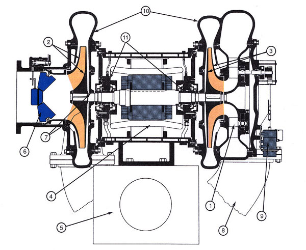
Figure 6-1: Two-stage centrifugal compressor. 1-Second-stage variable inlet guide vane. 2-First-stage impeller. 3-Second-stage impeller. 4-Water-cooled motor. 5-Base, oil tank, and lubricating oil pump assembly. 6-First-stage guide vanes and capacity control. 7-Labyrinth seal. 8-Cross-over connection. 9-Guide vane actuator. 10-Volute casing. 11-Pressure-lubricated sleeve bearing. Note that discharge opening is not shown.
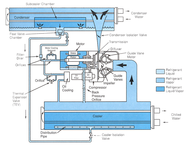
Figure 6-2: A hermetic centrifugal liquid chiller, single-stage compressor. Using HCFC-22, 300 to 600 nominal tons; using HFC-134a, 200 through 530 nominal tons. The system can utilize either R-22 or R-134a, which allows for conversion from R-22 to R-134a if needed. The unit has a microprocessor to control the system. Cutaway view showing the refrigeration cycle.
HELICAL SCREW COMPRESSORS
Screw-type compressors are generally and efficiently used in system with capacity above 20 tons of refrigeration. These compressors use a pair of helical screws, or rotors, which rotate together inside a chamber and force refrigerant from intake, low side of chamber toward the end high side of
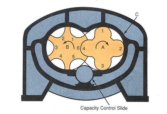
Figure 6-3: Cross-section of screw compressor. A-Male rotor. B-Female rotor. C-Cylinder. Vaporized refrigerant enters at one end and exhausts at other end.
As the gas is forced forward, it is compressed into shrinking gaps between the screw lobes, creating the compressing action. No valves are needed, other than service at the intake and exhaust ports. Because the rotors spin continuously, there is les vibration than with refrigeration and air conditioning book the chamber, reciprocating compressors. Helical (screw) compressors are made in open drive or hermetic configurations.
The rotors are termed “male” for the drive rotor, and “female” for the driven rotor. The male rotor, with more lobes, spins more rapidly than the female lobe. Capacity control is accomplished by a slide valve which opens in the compressor chamber and allows vapor to exit without being compressed some units are able to operate efficiently at only at only 10% of rated capacity.
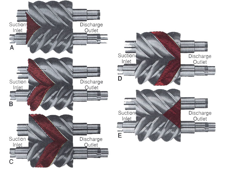
Figure 6-4: Basic operation of screw compressor. Revolving rotor compresses vapor. A-Compressor interlobe spaces being filled. B-Beginning of compression. C-Full compression of trapped vapor. D-Beginning of discharge of compressed vapor. E-Compressed vapor fully discharged from interlobe spaces.
RECIPROCATING COMPRESSORS
Reciprocating compressor use a piston sliding inside a cylinder to compress refrigerant vapor. Figure 4-29 shows the principle of operation of a reciprocating compressor. In figure 4-29A,the piston has moved downward in the cylinder, A. It has moved refrigerant vapor from the suction line through intake valve. From there the refrigerant vapor has moved into cylinder space. In Figure 4-29B, the piston has moved upward. It has compressed the vaporized refrigerant into a much smaller space (clearance space). The compressed vapor has been pushed through the exhaust valve into the condenser.
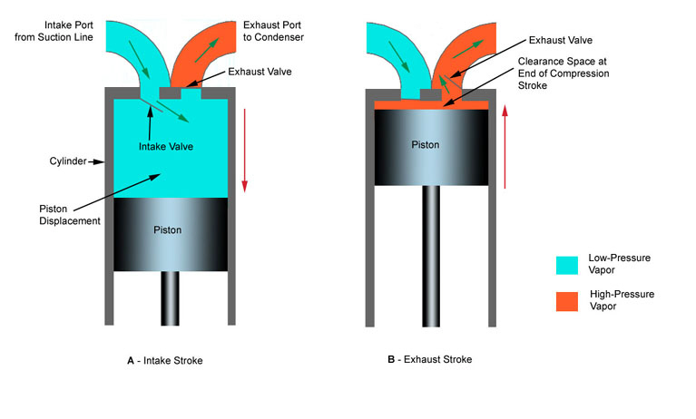
Figure 6-5: Basic construction of reciprocating compressor.
At he top of the stroke, the piston must come very close to the cylinder head. The smaller the clearance space, the greater the pressure that the piston stroke will create. This clearance may range between 0.010 and 0.020 inches (0.254 mm to 0.508 mm).
Small system may use two-piston compressor, while large industrial systems use multi-cylinder multi piston compressors. The compressor crankcase must be designed to dispose of the heat of compression. Compressor crankcases are usually make of cast iron and have fins for dissipating heat to air or in some cases water jackets, to dissipate the heat of compression to the water. In semi-hermetic and hermetic compressor, the cooling is provided by refrigerant from the suction line. Pistons in large reciprocating compressors have separate oil and compression rings. Oil rings, lower on the piston, are used to reduce the amount of oil entering the cylinder from the crankcase. In small systems, oil rings may be omitted and oil grooves used instead to control the oil flow. Compression rings are used to make tight seal against cylinder walls, ensuring that each stroke pumps as much refrigerant as possible.
CRANKCASE SHAFT AND CONNECTING RODS
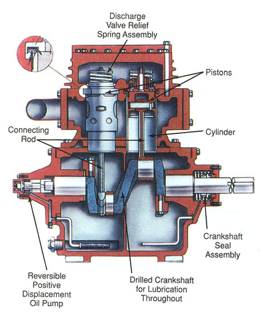
Figure 6-6: Cutaway view of small, external-drive, two-cylinder reciprocating compressor. The body is a lightweight alloy casting, Cast-iron cylinder liners are permanently cast into crankcase body.
In reciprocating compressors, the crankcase shaft converts rotary motion from the motor to reciprocating motion for the pistons. Crankshaft rotate within main bearing, which must firmly support the crankshaft and resist end loads placed on the shaft by the motor and connecting rods. The exact amount of the endplay should by specify in manufacturer literature.
Several types of linkages my be used to connect the connecting rod to the crankshaft:
CRANKCASE SEAL
In open – drive systems, the seal between the crankshaft and the crankcase is common source of problems. The seal is subjected to a great deal of pressure variations and must operate and must operate and seal whether the crankshaft is rotating or is stationary. Clearance must be accurate (to.000001 inch or .0000254 mm) between the rotating and stationary surfaces, and lubrication fills that tiny gap. The seal is commonly made of hardened steel a bronze, ceramic, or carbon. The absence of the crankshaft seal is the major advantage of the hermetic design.
The rotary-type seal is a simple, common seal that r0tates on the shaft in operation. A spring, in combination with internal pressure, forces the seal face against a stationary seal face.
The major source of problem with crankcase seals is leakage due to misalignment. Care must be taken when aligning the motor shaft to the compressor shaft so seal will be not stressed during the operation. The close tolerance as specified by manufacture of the compressor must be observed in both horizontal and angular directions. In most cases, the seal is lubricated by compressor oil pump. Make sure that the compressor is operated occasionally during the long shutdowns to keep the seal lubricated. A slight leakage after start up, during which a dry seal is lubricated with oil, may be normal.
A leaking seal can be detected with a refrigerant leak detector. To inspect a leaking seal:
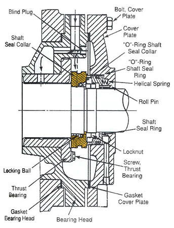
RECIPROCATING COMPRESSOR HEADS AND VALVE PLATES
Compressor cylinder heads are generally made of cast iron and are designed to hold the gaskets in place to provide positive seal between the valve plate, the cylinder block and head. Cylinder heads must have passages to admit suction gas into the cylinder. The head is generally affixed to the block with cap screws.
Intake valves are designed to admit refrigerant during the intake stroke and close during the compression stroke. Discharge valves are closed during the intake stroke and open at the end of the compression stroke. The valve plate is the assembly holding both valves tightly in place.
Valves are usually made of spring steel and designed to make a tight seal until the pumping action of the piston opens them. The mating surfaces of valves must be perfectly flat, and defects as small as 0.001 in. (0.0254 mm) can cause unacceptable leaks. In service, the valve must open about 0.010 in. (0.254 mm). Large openings will cause valve noise, while smaller openings will prevent enough refrigerant from entering and exiting the cylinder.
Operating temperature has great effects on valves durability. Intake valves operate in a relatively cool environment and have constant lubrication from oil vapors. Discharge valves are the hottest component in a refrigeration system, operating as much as 50 deg. F to 100 deg. F hotter than the discharge line, so the are more commonly a source of trouble than intake valves. Discharge valves must be fitted with special care. Heavy molecules of oil tend to accumulate on them, causing carbon buildup and interfering with valve performance. Discharge valves and oil will be damaged by temperature hotter than 325 deg. F to 350 deg. F (163 to 177 deg. C). In general, the discharge line temperature should be kept blow about 225 deg. F to 250 deg. F. (107 to 121 deg. C).
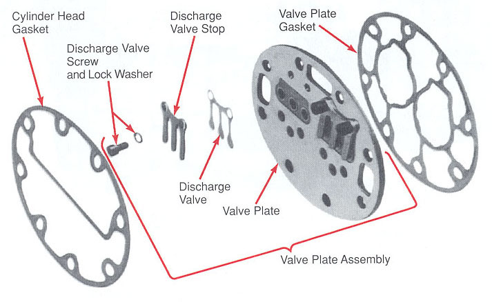
Figure 6-7: Reciprocating compressor valve plate assembly.
Discharge valves may have relief springs to enable them to open abnormally wide if slug of liquid refrigerant or oil enter the compressor piston from the suction line or the compressor crankcase.
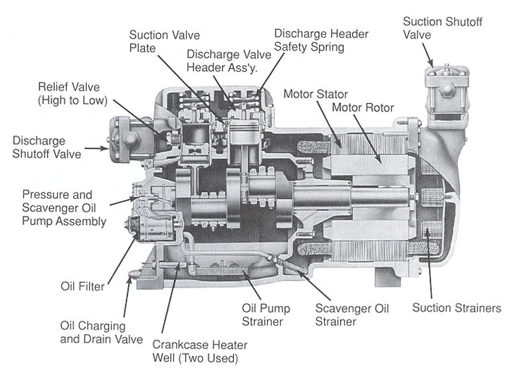
Figure 6-8: A commercial, hermetic reciprocating compressor. It has four banks of two cylinders each (four connecting rods on each crankthrow) and is bolted for ease in servicing.
ROTARY COMPRESSOR
Rotary compressors use one or more blades to create the compressing action inside a cylinder. Unlike the reciprocating compressor, no piston is used. There are two basic types of rotary compressors:
In both types, the blade must be able to slip within its housing to accommodate the motion of the rotor, which rotates off center within the cylinder. Inlet (suction) ports are much larger than discharge ports. There is no need for intake (suction) or discharge valves; however, check valves are desirable are desirable in the suction line to prevent oil and high-pressure vapor from entering the evaporator when compressor is not operating.
ROTATING BLADE (VANE) COMPRESSOR
In a rotating vane design, a rotor (shaft) rotates inside a cylinder, but the center axes of the cylinder and the shaft are not identical. The rotating rotor (shaft) has several precision-machined grooves that accept the sliding vanes. As the shaft spins, these vanes are forced against the cylinder by centrifugal force. As gas enters the compressor from the suction line, the vanes sweep it around. Because the rotor is not centered in the cylinder, the space containing the gas decreases as the vanes force the gas around the cylinder. The result is gas compression. When the gas reaches minimum volume and maximum compression, it is forced out the discharge port. The clearance volume of this system is very low and the compression efficiency very high.
Rotating vane compressors are commonly used for the first stage of cascade system. Rotary vane compressors may have between two and eight vanes; large systems have more blades. The edge of the blade where it meets the cylinder wall must be accurately ground and smooth or leakage and excess wear will result. The blade must also be precisely fit into the slot in the rotor.
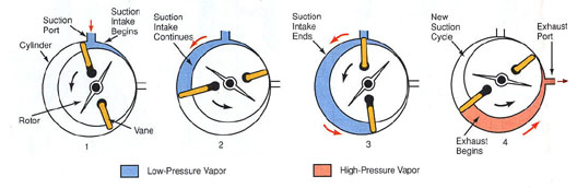
Figure 6-9: A rotary blade compressor. Black arrows indicate direction of rotation of rotor. Red arrows indicate refrigerant vapor flow.
STATIONARY BLADE (DIVIDER BLOCK) ROTARY COMPRESSOR
In the stationary blade system, a sliding blade in the cylinder housing separates the low-pressure vapor from the high-pressure vapor. An eccentric shaft rotates an impeller in a cylinder. This impeller constantly rubs against the outer wall of the cylinder. As the impeller revolves, the blade traps quantities of vapor. The vapor is compressed into a smaller and smaller space. The pressure and temperature builds up. Finally the vapor is forced through the discharge port.
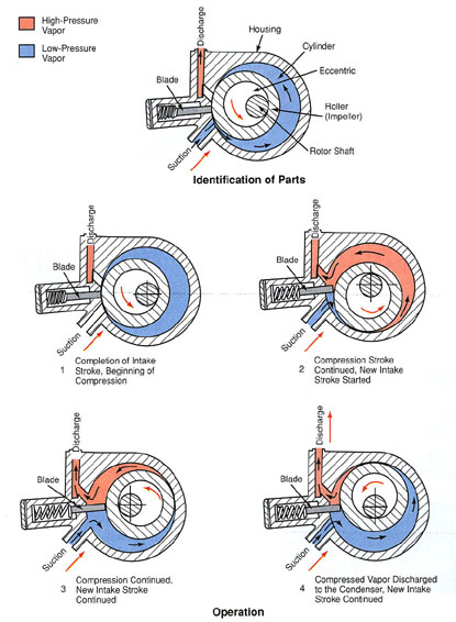
Figure 6-10: Rotary compressor. Stationary blade or divider block is in contact with an impeller.
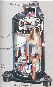
Figure 6-11: Hermetic, single stationary-blade rotary compressor.
SCROLL COMPRESSOR
In a scroll compressor, compression is performed by two scroll elements an orbiting scroll and a fixed scroll. One scroll “the fixed scroll” remains stationary. The other scroll “the orbiting” scroll rotates through an offset circular path around the center of the fixed scroll. This movement creates compression pockets between the two scroll elements. Low pressure, suction gas is trapped in each peripheral pocket as it is formed; continued motion of the orbiting scroll seals the pocket, which decreases in volume as the pocket moves toward the center of the scroll. Maximum compression is achieved when a pocked reaches the center where the discharge port is located and the gas is discharged. During this compression process, several pockets are being formed at the same time.
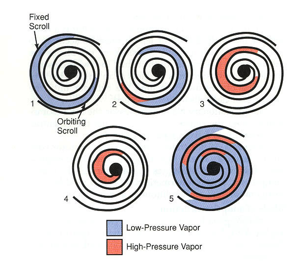
Figure 6-12: Compression in the scroll is caused by the interaction of an orbiting scroll mated within a stationary scroll. 1-Gas is drawn into an outer opening as one of the scrolls orbits. 2-As the orbiting motion continues, the open passage is sealed off and the gas is forced to the center of the scroll. 3-The pocket becomes progressively small in volume. This creates increasingly higher gas pressures. 4-Discharge pressure is reached at the center of the pocket. Gas is released from the port of the stationary scroll member. 5-In actual operation, six gas passages are in various stages of compression at all times. This creates nearly continuous suction and discharge.
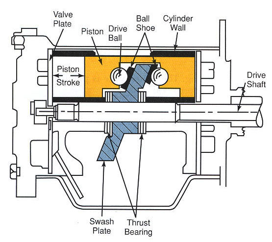
Figure 6-13: Cross section through a swash plate reciprocating compressor. As drive shaft and swash plate revolve, double-end piston is moved back and forth in cylinder.
The suction process from the outer portion of the scroll and the discharge from the inner portion are continuous. This continuous process gives the compressor very smooth operation.
Compression is a continuous process without conventional suction and discharge valves. To prevent the compressor from running backwards after the power has been switched off, a check valve is located directly above the fixed scroll discharge port.
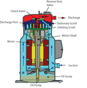
A: Cutaway diagram of a scroll compressor. 
B: Basic compression representation of a scroll compressor. Orbiting scroll orbits the fixed scroll creating a smooth, constant compression inward towards the discharge port at the center.
OIL SYSTEMS FOR COMPRESSORS
Reciprocating compressors use generally two types of lubricating systems:
Rotary compressors
Require a film of oil on the cylinder, blades and roller. Some machines propel the oil by the sliding action; others use an oil pump.
Centrifugal compressors
Operate at high speed and may have elaborate oil control systems, with a pump, oil separator, reservoirs to lubricate bearings during cast-down, oil filter, relief valve, and oil cooler.
Helical screw compressors
Need oil to cool, seal, and silence the rotors; they generally have a forced lubrication system. A positive displacement pump may operate independently of the compressor, ensuring complete lubrication at the compressor start up. Oil is separated, piped to an oil sump (reservoir). Cooled and delivered to the bearings and ports for injection into the compression chamber. The oil sump (reservoir) has a heater to prevent oil dilution by refrigerant during the off-cycle.
Scroll compressors
Require oil to cool and seal between orbiting and stationary scroll. Oil is driven to the scrolls by centrifugal action through hole in a shaft of the motor and orbiting scroll.
Three devices are generally used in industrial refrigeration system to control system oil: an oil separator, an oil level regulator, and oil reservoir. Other elements, such as oil strainers, solenoid and isolating valves, may be needed to complete the system. A regular system oil test should be perform, to detect damaging acidity in the refrigeration compressor oil.
Promoting oil return
Oil in direct expansion or dry evaporator systems must be swept back to the compressor by the flow of refrigerant. The velocity in the evaporator tubes must be sufficient to carry the oil back.
The velocity of about 700 feet (214 m) per minute are required in horizontal lines and about 1500 feet (457m) per minute in vertical lines are needed.
Several additional measures will help to assure proper oil return to the compressor. Slope the refrigeration lines toward the compressor. Ensure adequate refrigerant velocity in the suction line by making it proper size, not oversize. High viscosity oil (as measured in evaporator condition) is more resistant to return by refrigerant flow. Oil that readily dissolves refrigerant remains more fluid than oil without refrigerant. The amount of refrigerant dissolved in the oil varies according to pressure and temperature conditions in various parts of the evaporator, and the nature of the two fluids.
Oil return is more difficult in low-temperature evaporators, because oil becomes more viscous as the temperature and pressure of the refrigerant becomes low. High compression ratio also decreases oil return, because the suction gas is less dense. Thus adequate suction line velocity is especially important in low-temperature evaporators.
Oil will not be swept back to the compressor in a flooded evaporator, so an oil return line is required. In some systems, a special chamber is connected to the evaporator to allow refrigerant to be boiled from the oil before the oil is returned to the compressor.
DISCHARGE LINE
The discharge line on the high side of the system, connect the compressor to the condenser. The line is commonly copper tubing connected by brazing. The discharge may contain; Vibration absorber, Muffler, Oil separator, pressure control valves, and by pass or service valves.
Vibration Absorber
Both the suction and discharge lines transmit vibration from the compressor to other cooling system components. This vibration can cause unwanted noise and deterioration of refrigerant tubing leading to leaks of refrigerant.
On small system with small-diameter soft copper tubing, the vibration absorber may consist of a coil of tubing. Flexible metallic hose, with ID at least as large as the connected tubing, is preferable for larger systems. This section of tubing may be terminated by OD socket, threaded male ends or flanges. Refrigerant traveling with high velocity along the convoluted inner diameter of the absorber may cause a whistling sound. Vibration absorbers are not designed for compression or extension, so they mast be oriented parallel to a compressor crankshaft, not at right angles to it.
Muffler
A muffler is used to reduce the transmission of reciprocating compressor discharge pulsation and noise to the piping system and to the condenser. A muffler is a cylinder with baffle plates inside. In general, mufflers, which create a large pressure drop, are more effective than those with less restriction. Both the volume and density of the gas flow through the muffler affect muffler performance.
Oil separator
An oil separator is a container with a series of baffles and screens placed in the discharge line. The discharge vapor with oil fog entering the oil separator is forced to turn and collide against the baffles and screens, allowing droplets of oil to combine into large drops, which drip to the sump at the bottom. The sump allows sludge and contaminants to settle out and may have a magnet to attract ferrous particles. When sufficient oil has accumulated in the sump, it lifts a float and flows back to the compressor crankcase, propelled by the oil pressure in the oil separator.
Oil separators are most often found on large and low temperature systems. They are mandatory on ammonia systems.
CONDENSER
The condenser is the refrigeration circuit high side component, which allows the hot high-pressure refrigerant gas to loose its latent heat of condensation to the environment. This loss of heat causes the gas to condense into high-pressure liquid that can piped to the metering device. The heat rejected by the condenser enters the system in the evaporator and the compressor. Due to inefficiencies and other heat gains, a condenser in an open system must dispose of about 1.25 times the heat gained in the evaporator. Condensers in hermetic systems must also dispose of heat from the motor windings.
Many different types of condensers are in use, depending on the function, and the means of disposing of the heat. The two basic categories “water cooled” and “air cooled” are classified by the medium used to remove heat. The basic design goal of a condenser is to remove the most heat at the lowest cost, and space requirements.
Water and air are usually plentiful and economical condensing media. Water can remove large amounts of heat quickly and efficiently, which allows the condenser to be relatively small and makes water-cooled condenser more economical when suitable is available. However, water may be scarce or chemically unsuited for condenser cooling use. In addition, water-cooled condensers are subject to scale, fouling, freezing, and corrosion.
Air-cooled condensers must be large than water-cooled units, but are not subject to freezing or water problems. Air-cooling is used when water is unavailable, expensive or chemically unsuitable.
Fins, wires, or plates may be fastened to condenser tubing to increase the surface area and the ability to dispose of the heat of condensation. Fans or pumps are commonly used to increase the flow of the condensing medium. Such enhancements increase the sub-cooling of the refrigerant, increase the rate of heat transfer, and decrease the oval size of the condenser.
AIR COOLED CONDENSER
Air-cooled condensers relay on fans to move air across the tubes and fins to remove heat from the refrigerant. Shrouds are used to increase fan efficiency by directing all the airflow across the condenser tubes. Different type of fins can be used to increase the surface area of the condenser. Proper heat transfer in air-cooled condensers can be achieved only if the condenser surface is clean.
The air-cooled condenser must be designed to work in the hottest ambient conditions, when the heat transfer will be slowest and the cooling load is likely to be the greatest.
Outdoor air-cooled condenser operating in cold weather presents a special system design challenge. Special precautions are needed to protect an outdoor, air-cooled condenser from low ambient temperatures. The major problem is that the refrigerant will not flow through the metering device unless head pressure is sufficient, and the cold ambient temperatures reduce head pressure.
For air-cooled condenser to operate in cold ambient temperatures the system may require any of the following devices or combination of:
Disclaimer - While Berg Chilling Systems Inc. ("Berg") makes reasonable efforts in providing accurate information, we make no representations or warranties regarding the accuracy of any content therein. We assume no liability or responsibility for any typographical, content or other errors or omissions. We reserve the right to modify the content of this documentation without advance notice.
by Oldrich Bocek(1939-2003)
Thermal Management Expert
Berg Chilling Systems Inc.